[Summary] Truth Table and Logic Gate
X
Advertisements
Loading...
On this occasion, we will discuss in more detail the truth table of logic gates.
For those of you who are looking for the complete material, take a good look at the review below until it's finished.
list of contents
Understanding Logic Gates

Advertisement
Logic gates are often used to design and design a controlled system by a digital input and produces an output that depends on the logic circuit alone.
For the understanding of logic gates / logic gates themselves, namely a binary number input processing process with boolean mathematical theory.
As we all know that binary numbers consist of the numbers 1 and 0.
This logic gate is described by using a truth table.
If it has a true value, it will be indicated by using the number "1". Conversely, if it has a value of false (false) it will be designated with the number "0".
While the logic gates used in Digital Electronics systems basically use a series of electronic components, such as diodes, integrated circuits (ICs), relays, transistors, optics or Mechanical Elements.
Logic Gate Function

Logic gates have a function to perform a basic logic function to create an integrated digital circuit.
Most of these logic gates use binary numbers 0/ 1 which can also be referred to as true or false. In general, it consists of two input values and one output value.
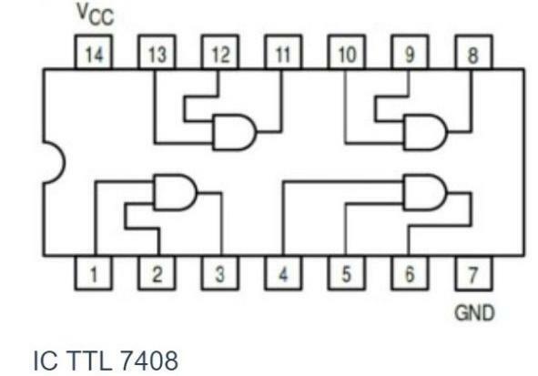
Simple logic IC components such as the TTL 7408 Logic IC may consist of only a few logic gates.
In simple electronic circuits, be it TTL/CMOS ICs which consist of several logic gates commonly used in circuits such as:
- Counter series
- Flip-flop circuit
- Build a demultiplexer
- Build a multiplexer
- Set security with secret lock code
- A decoder set, its function is to convert a binary number to another number
- Encoder set, its function is to convert a number into binary form.
In the IC Microprocessor (microprocessors) complex can also consist of millions of logic gates. This IC component is known as a chip.
Example:
The INTEL Stratix 10GX chip with a total logic of 10.2 million logic, as shown below.
Advertisement

By combining thousands or even millions of logic gates, a very complex digital operation can be created.
The maximum number of logic gates on a chip can be determined by the size of the microprocessor chip divided by the size of the logic gate.
Truth Table

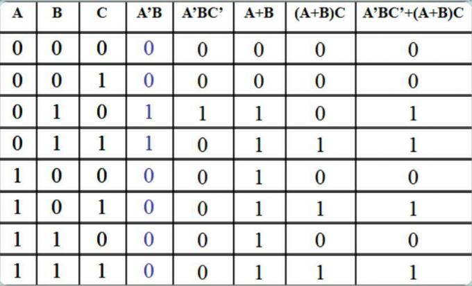
Truth table or also commonly referred to as truth table is a table that is used to see the truth value of a statement.
In this case, the truth table can also be defined as a table whose contents are various combinations of input variables that will produce logical outputs or outputs.
In binary mathematical logic, this one table is usually used to analyze the truth of a statement in the world of electronics that is identical to the input.
Because there are 7 logic gates, there are also 7 logic gate truth tables that can be described as shown above.
Types of Logic Gates
There are several types of logic gates that are very commonly used, including the following:
1. AND Gerbang gate

The first or basic type that you should know about is the AND gate.
This AND gate requires two or more inputs to produce one output.
If all or one of the inputs is a binary number 0, then the output will be 0.
Meanwhile, if all inputs are binary 1, then the output will be 1.
2. OR Gerbang Gate

The second type is the OR gate.
As with the previous gate, this one gate will also require two inputs to produce an output.
This one OR gate will produce an output of 1 if all or one of the inputs is a binary number 1.
Advertisement
Meanwhile, the output will produce 0 if all the inputs are binary 0.
3. NOT Gate

The next type is the NOT gate.
This NOT gate has a function as an inverting condition. If the input is 1, the output will be 0 and vice versa.
4. NAND Gate

Then there are also NAND gates.
NAND gate is a combination of AND gate and NOT gate.
Therefore, the output produced from this one NAND gate is the opposite of the AND gate.
5. NOR Gate

Next up is the NOR gate.
This one NOR gate is a combination of OR gates and NOT gates.
Which will produce the output of the NOR gate is the opposite of the OR gate.
Advertisement
6. XOR Gate

The next type is the XOR gate.
This XOR gate requires two inputs to produce one output.
If the inputs are different (for example: Input A=1, input B=0) then the resulting output will be a binary number 1.
Meanwhile, if both inputs are the same, it will produce output with a binary number 0.
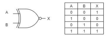
7. XNOR Gate

The last type is the XNOR gate.
This XNOR gate requires two inputs to produce one output.
If the input is different (for example: input A = 1, input B = 0) then the output that will be produced is a binary number 0.
Meanwhile, if both inputs are the same, it will produce output with binary number 1.
If you are majoring in informatics engineering, information Systems, as well as electronic engineering, you will definitely meet this Logic Gate Truth Table material.
Therefore, with this article, it is hoped that it can help your learning process later, starting from the meaning, function, and also its types.
