
Understanding Assembled Maps, Objectives, and Working Standards
Education. Co. ID – On this occasion we will discuss the assembled map or also known as the Assembly Chart, for a complete explanation read this article:

Definition of an Assembled Map (Assembly Chart)
Assemblies Map is a graphic depiction of the flow sequences of components and sub-assemblies to the assembly of a product. It will be seen that the assembled map shows an easy way to understand:
- The components that make up the product
- How do these components come together
- Components that make up a part-assembly
- Flow of components into an assembly
- Linkages between components and assemblies
- Overview of the assembly process
- Time sequence of components joining together
- An early description of the material flow pattern
Purpose of Working on Assembled Charts (Assembly Chart)
The main purpose of an assembly map is to be able to show the interrelationships between components, which can also be described by a 'draw-out'. These techniques can also be used to teach unskilled workers to know the order in a complex assembly.
Working Standards for Assembled Charts (Assembly Charts)
Working Standards of this Assembly Chart are as follows [Apple, 1990, p. 139]:
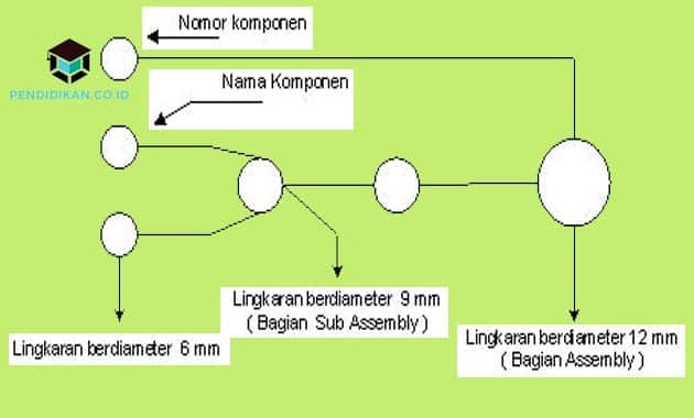
1. The last operation that indicates the assembly of a product is represented by a 12 mm diameter circle and must also be written to the right of the circle.
2. Draw a horizontal line from the circle to the left, place a 6 mm diameter circle on the end, show each component (name, part number, quantity, etc.) assembled in a process that.
3. If what you are dealing with is an assembly of parts, then draw the line in part and end it with a circle with 9 mm in diameter, the line indicating the independent component must be drawn to the left and also ends with diakhiri 6mm diameter.
4. When the last assembly operation and its components have been recorded, draw a short vertical line from the 9 mm circle line to the above, entering the 12 mm circle indicating the assembly operation before the assembly operation described in step 2 and step 3.
5. Then check the map again to make sure that all the components are listed, enter the assembly operating numbers the part into a circle (if necessary), the components listed on the left are numbered sequentially from top to bottom of the sub-section assemblies.
Circles indicating assemblies or also sub-assemblies do not necessarily indicate work station paths or also assembly trajectories or even people trajectories, but only really indicate the required order of operations worked on. The time required for each of these operations will determine what the operator must do.
That's all and thank you for reading about Understanding Assembled Maps, Objectives, and Work Standards, Hopefully it can be useful for you.
See AlsoDefinition of Exploitation, Types, Examples, Impacts and According to Experts
See AlsoDefinition of Achievement Work Behavior
See AlsoDefinition of Social Control, Types, Functions, Methods and Forms